A&A CORVETTE C7 SUPERCHARGER SYSTEM
INSTALLATION INSTRUCTIONS FOR THE C7 CORVETTE

INSTALLATION INSTRUCTIONS FOR THE C7 CORVETTE
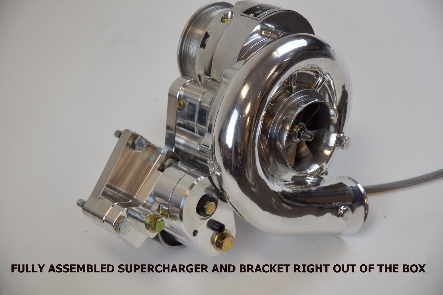
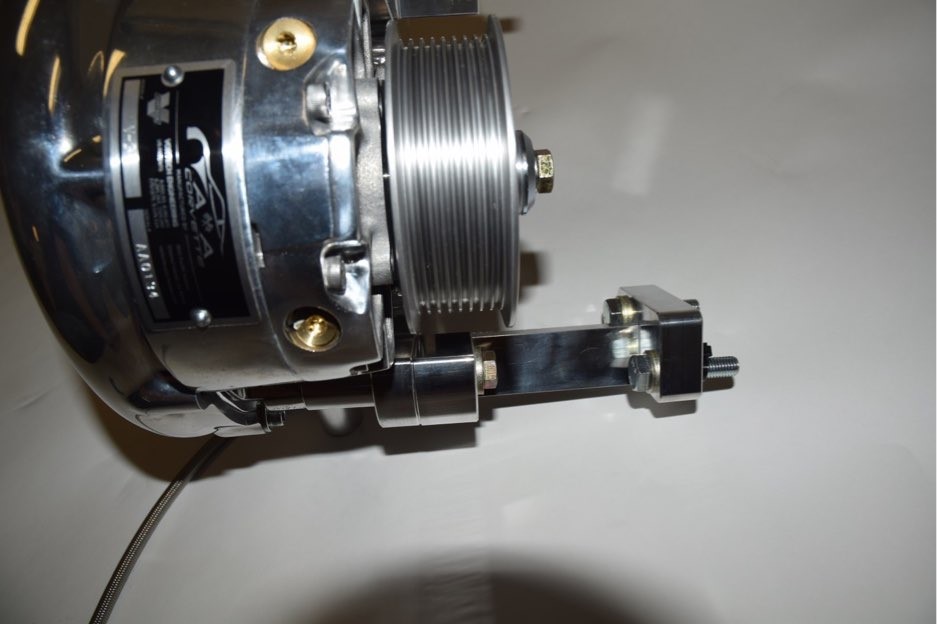
A&A CORVETTE PERFORMANCE C7 SUPERCHARGER

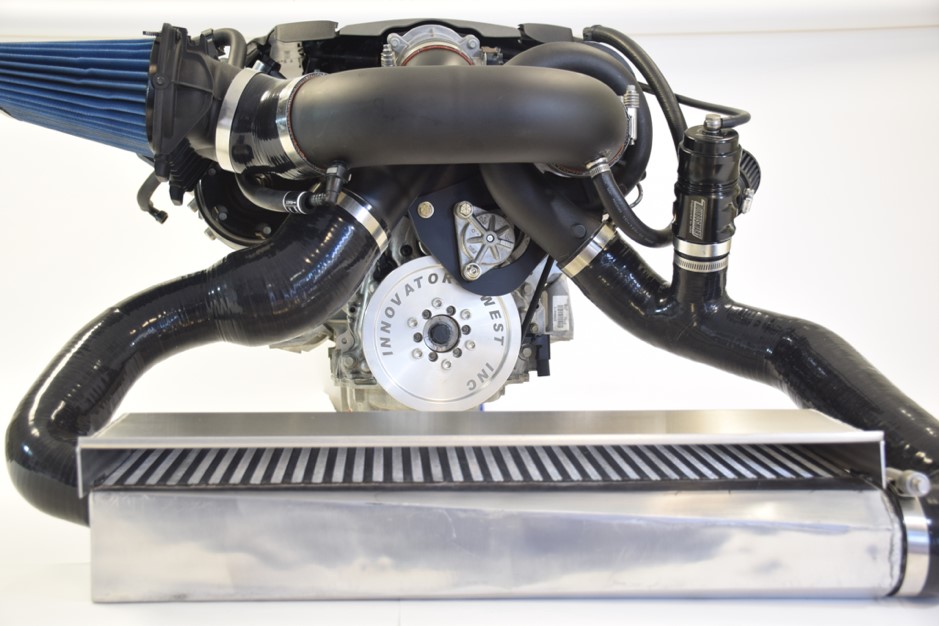

GETTING STARTED
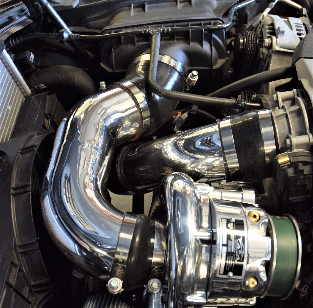
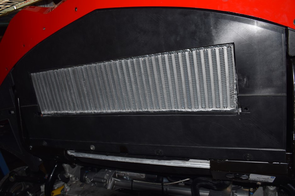
The supercharger install is very straightforward and can be performed at home with basic mechanical skills and tools. Once finished, everything will fit under the stock hood and all covers, including the radiator to hood heat extractor will fit back on the vehicle. The car will need to be raised on jackstands or a lift for proper access to the underside of the vehicle.
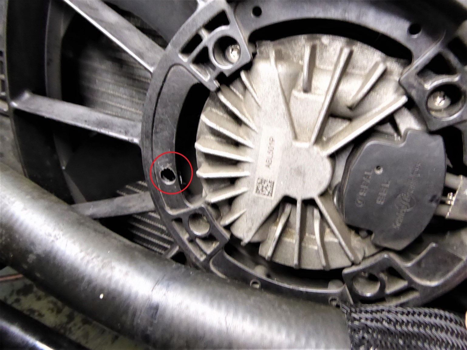
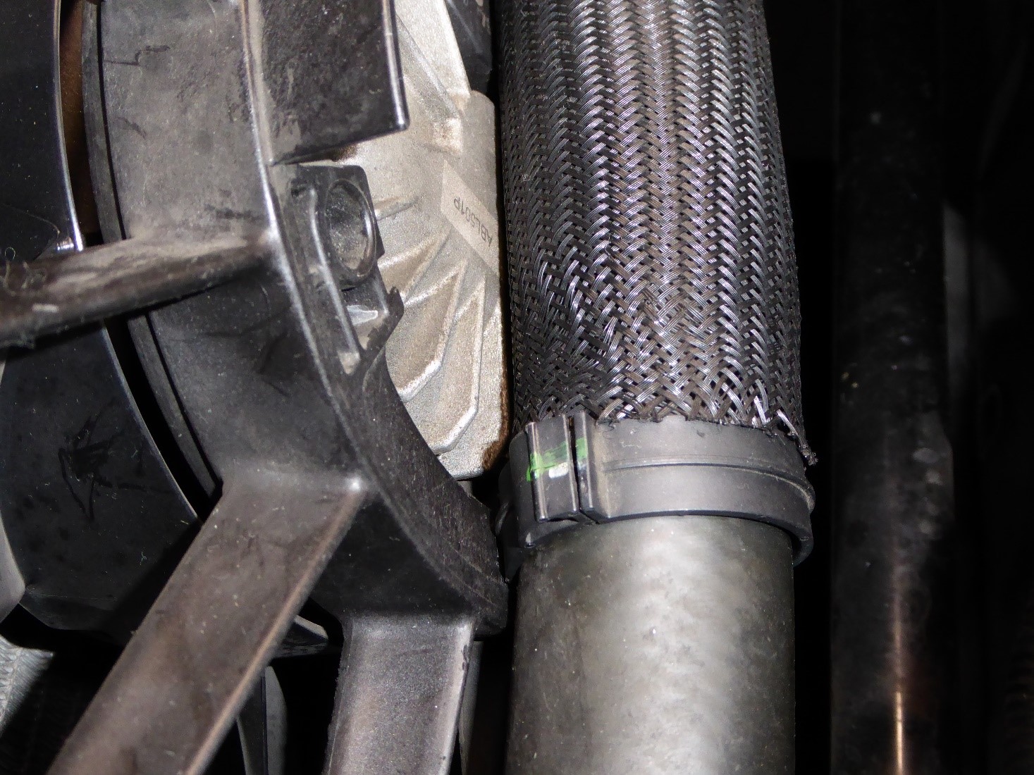
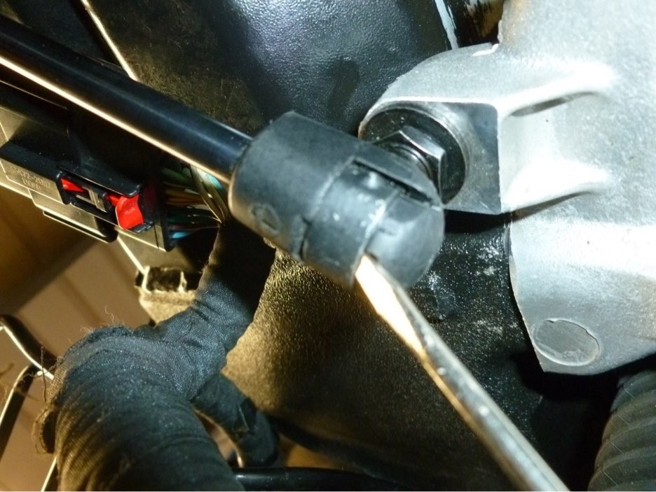
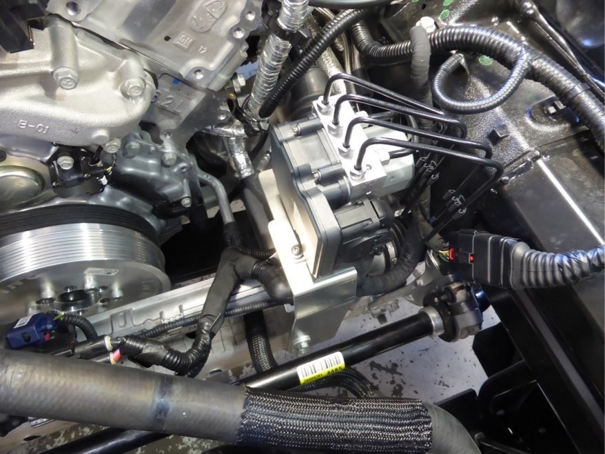
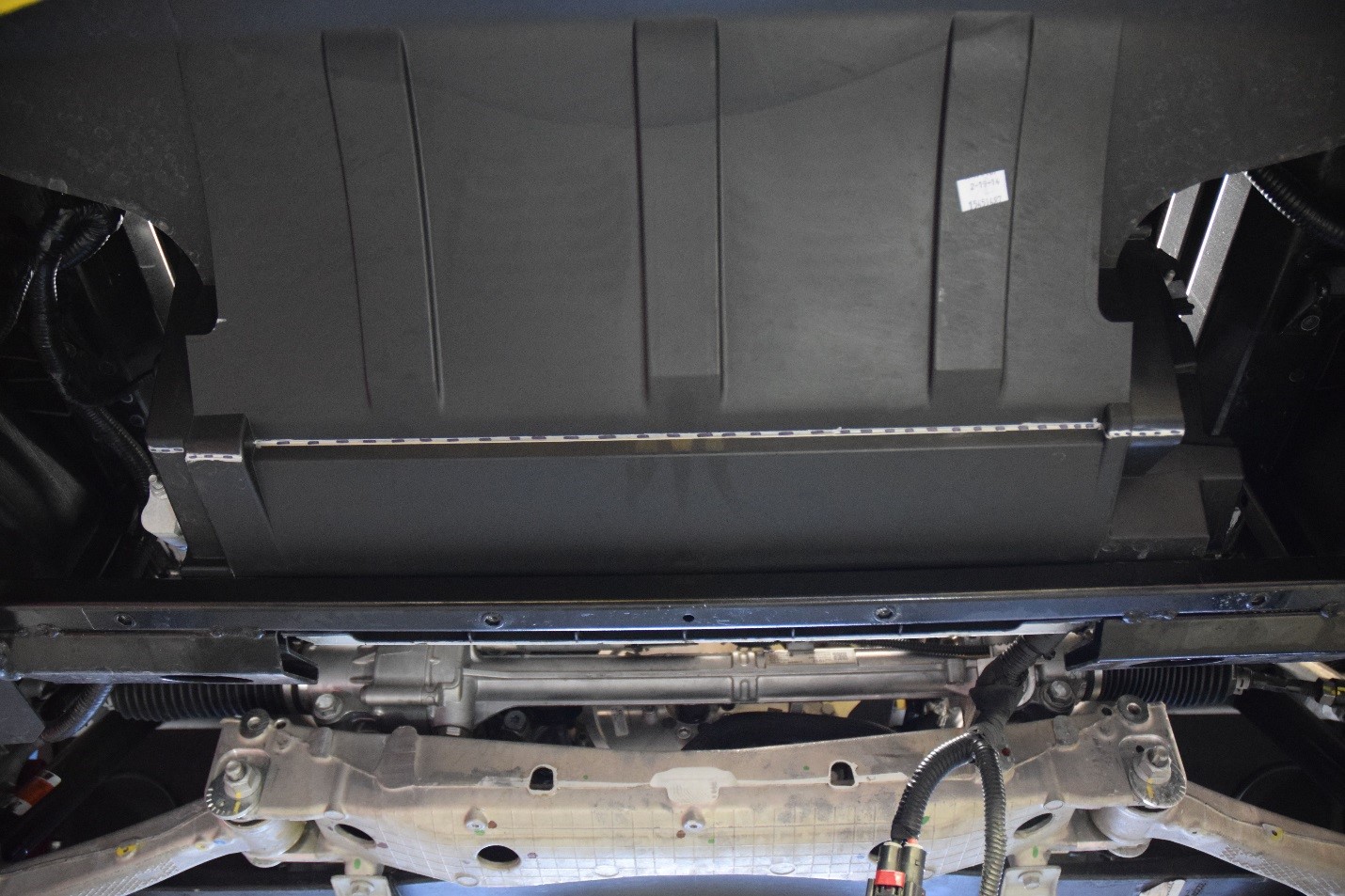
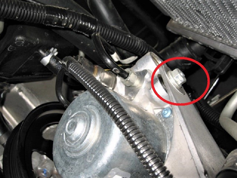
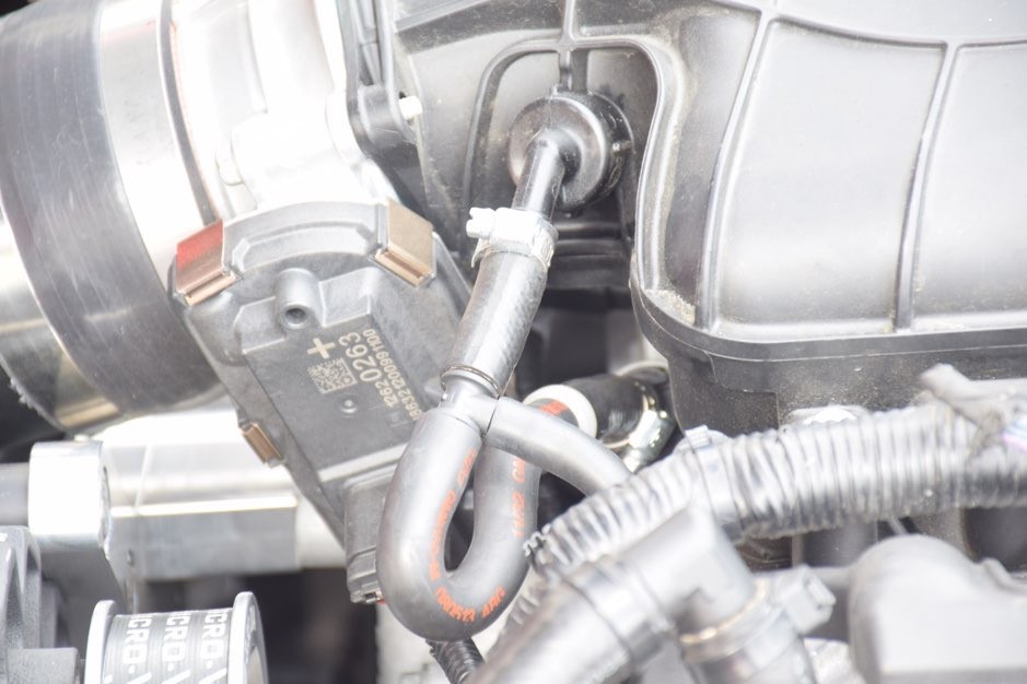
(HOSE SECURED WITH FACTORY PUSH PIN RETAINER)
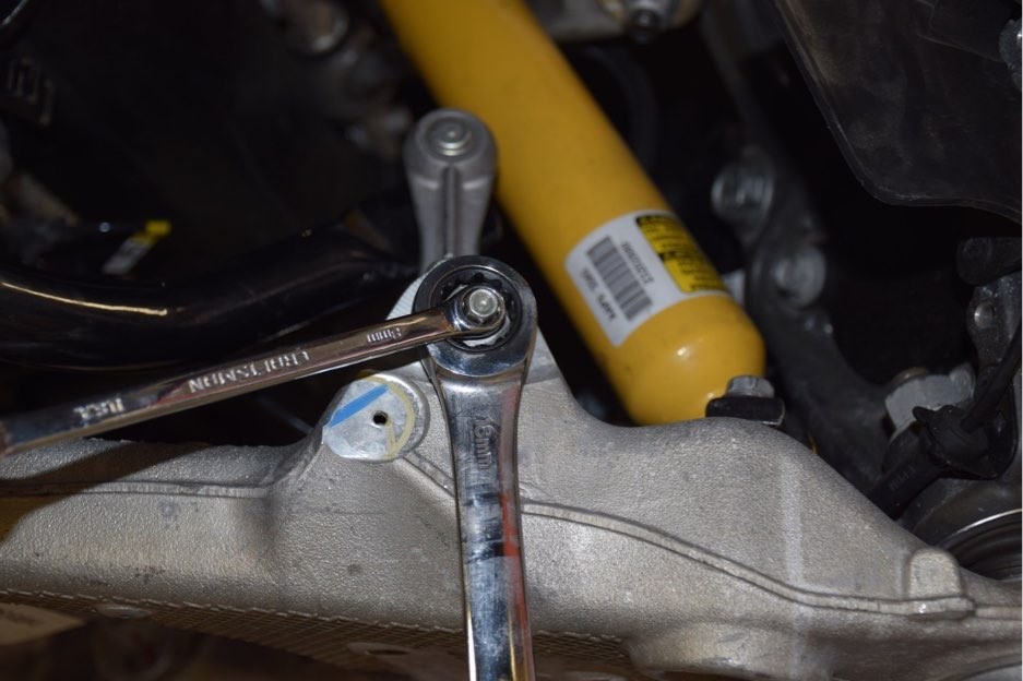
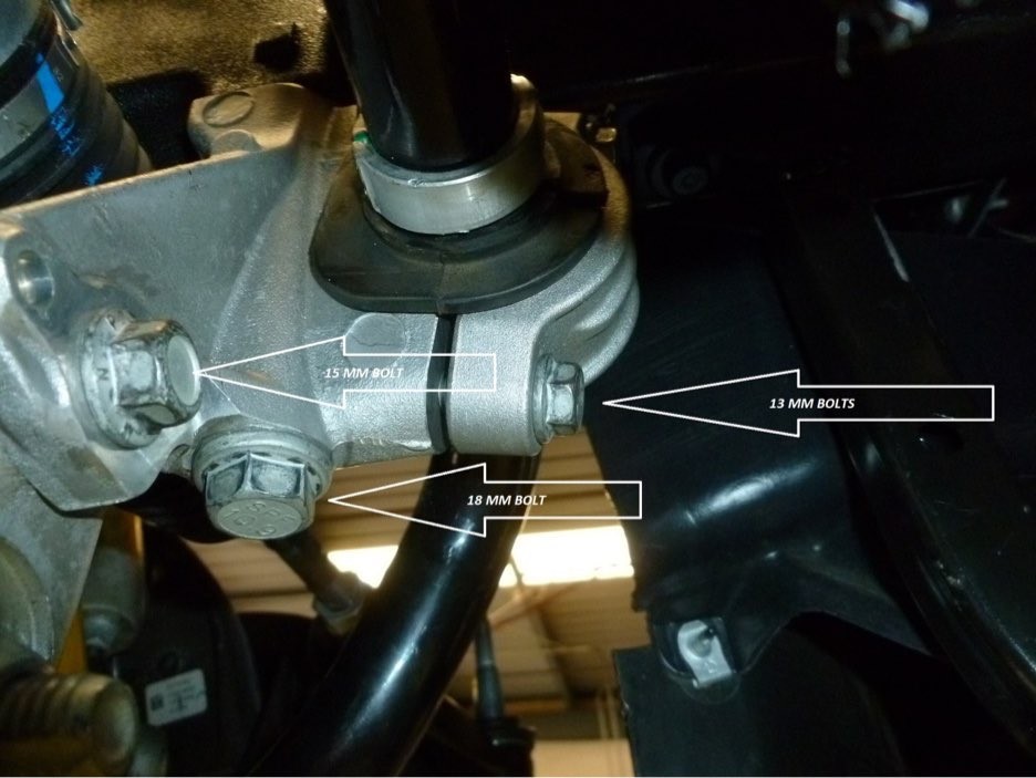
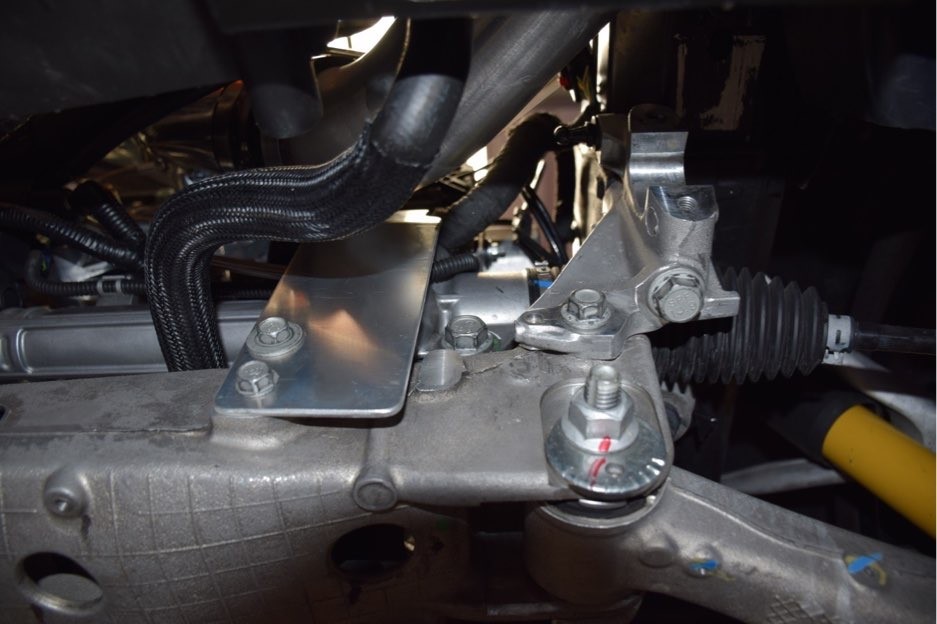
(SWAY BAR END LINK REMOVAL)


We want you to have the best experience possible when dealing with us both before and after the sale. You can always talk to a sales manager, the owner and head designer, or one of our techs who is infinitely knowledgeable on how the products operate and are installed. You won’t get a minimum wage customer service rep that knows nothing outside his or her script. You’ll get great advice based on many years of experience every time.
We’re happy to help you with your DIY install questions or product inquiries even after hours. The phones forward to either a Manager or Owner to help with both. Remembering that we are on Pacific time, you can generally get help until 9PM on weekdays and weekends alike. It’s something we started when the company was very young and have found it to be an invaluable resource to our customers.
SHARE THIS PAGE!