A&A CORVETTE
DUAL PUMP FUEL SYSTEM INSTALLATION
Fits 2003-2013 Corvettes
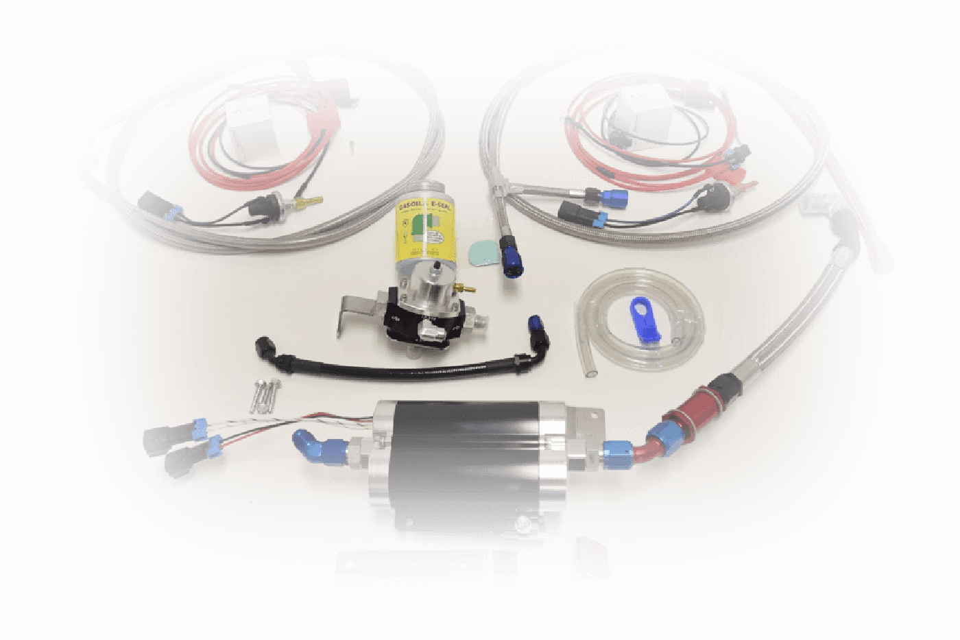
A&A CORVETTE PERFORMANCE DUAL PUMP FUEL SYSTEM
INSTALLATION INSTRUCTIONS - 2003 to 2013 MODELS
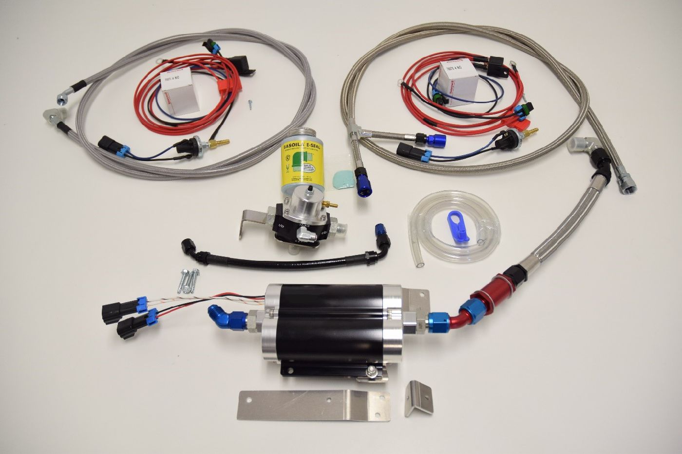
1. GETTING STARTED
Proper installation of this fuel system requires general automotive mechanic knowledge and experience. Please browse through each step of this instruction manual prior to beginning the installation to determine if you should refer the job to a professional installer/technician. Follow all safety precautions needed for handling gasoline. Please contact A&A Corvette if you need assistance.
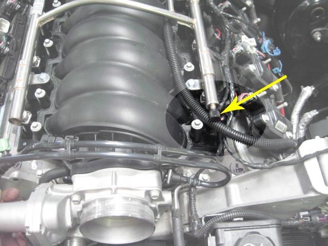
1.1 The gas tank will need to be drained as low as possible. Raise the car on a suitable lift or jack stands. Relieve the fuel pressure by depressing the Schrader valve on the end of the driver’s side fuel rail. Catch the escaping fuel in an appropriate container.
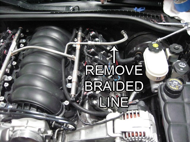
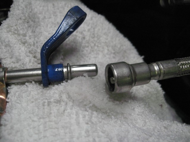
1.2 Using the supplied quick disconnect tool, remove the braided fuel line that runs from the hard factory fuel line to the fuel rail. Catch the escaping fuel in an appropriate container.
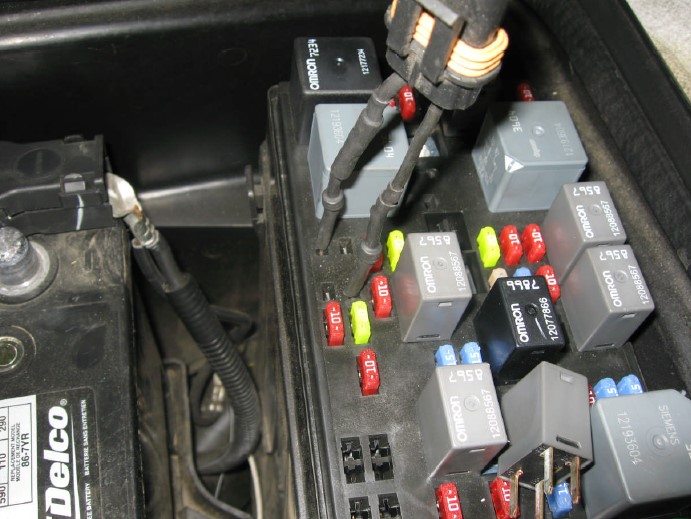
1.3 Attach the supplied clear hose to the factory hard line and route the other end into a large gas can or similar container. Remove the fuel pump relay from the fuse box located in the engine compartment. Check your owner’s manual to verify the correct location for the relay. Insert a jumper wire into the fuse box terminals as shown. This will run the fuel pump and drain the tank into the gas can. Continue to drain the tank until no more fuel flows. Disconnect the battery when the draining is completed.
2. FUEL LINES
2.1 Remove the rear driver side wheel. Remove the aluminum tray that holds the tank in place. With the tank empty, it will only drop an inch or so when the tray is removed. Remove the inner left rear wheel liner.
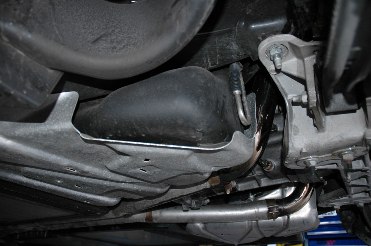
2.2 Locate the pump and pump feed hose assembly. The C6 feed hose consists of a double female 45 degree AN fitting, fuel filter, 15 inch -10 AN hose and the 90 degree tapered fitting that screws into the tank. The 2003- 2004 C5 hose is slightly different. It consists of a 9” -10 AN hose, fuel filter, another 9” 10 AN hose and the 90 degree fitting. The lines come preassembled for easy reference.
Loosely attach the assembly to the pump as shown and put the assembly in the left fender well. The pump will mount to the frame with screws as far forward as you can get it. The aluminum brackets will line up nicely with the bottom of the frame rail and the bulkhead. The angles of the fuel line – filter assembly will show you where the pump will best fit. The fuel line assembly should follow the contour of the tank and end up at the rear of the tank.
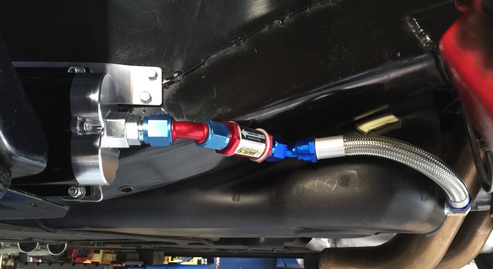
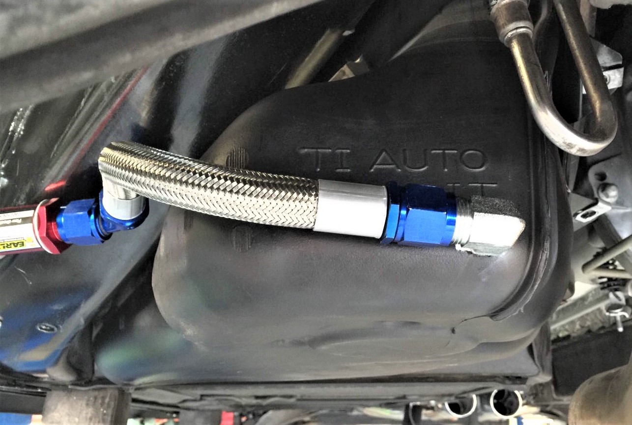
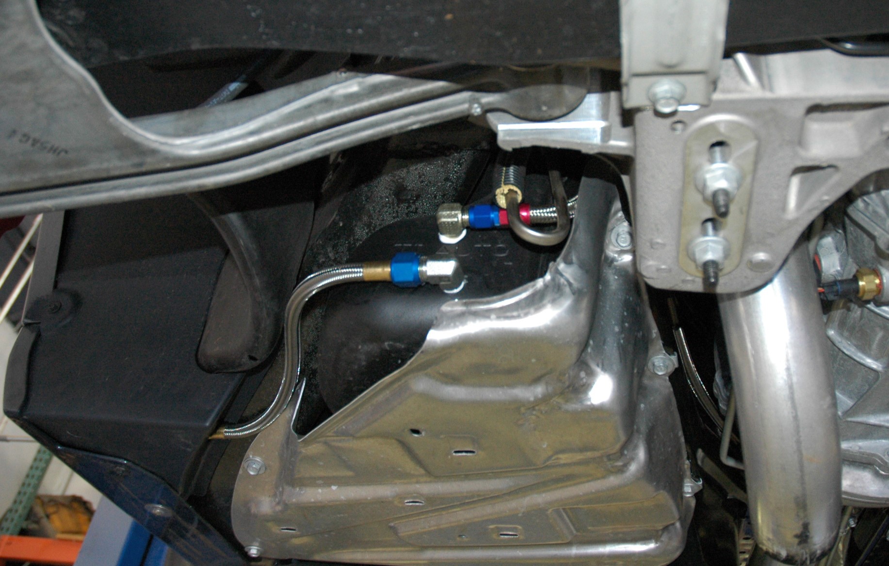
2.3 The 15” line should line up with the rear surface of the tank. Locate the spot where the 90 degree end will meet the tank with the line following the frame contours and mark it. Make sure the spot is as low as possible on the back of the tank. Remove the pump assembly for now. You will be drilling a hole in the tank at this spot. The fitting is a tapered thread and will tighten up as it is screwed in. Drill the hole with an 11/16” bit (Use an air powered drill. DO NOT use an electric or battery powered drill around fuel). Some fuel will definitely come from the hole, so be prepared with a pan or container to catch it. Tap the hole with a 1/2 NPT tapered tap. Tap just deep enough so that the fitting will start in the hole. This way the tapered fitting will get extremely tight as it goes into the hole. The tank is quite thick and made of a nylon sort of material. It will seal on the tapered thread as it goes in. Put some of the provided “Gasoila” sealer on the tapered fitting and install it in the hole. You’ll find a small packet of the sealer with your hardware. The end of the fitting should face the driver’s side when finished. Attach the fuel pump feed line assembly to the tank fitting and secure it at an upwards angle just to stop the dripping for the time being.
2.4 Remove the driver side front wheel. Remove the access panel behind the left front wheel. Locate the long braided fuel line with two quick-connect ends and the two fuel pump relay wires. Tape the ends of the long red wires to the single female end of the fuel line and push it through the rocker panel until it comes out the back side. Tape over the fitting so as not to get dirt in the fuel line. Un-tape the wires and plug them into the wire harnesses on the pumps.
Attach the braided hose to the pump outlet and tighten. Find the right spot on the frame, using the brackets and intake fuel line assembly to guide you. The supplied self-tapping screws are used to attach the pump brackets to the frame. Check the position of the pump before screwing it in place. Clean some paint off and attach the ground wires to the frame.
The front of the fuel line snaps directly onto the factory fuel rail and the original hard line that runs up the firewall. Running it up and over the master cylinder seems to work best. Your feed line is now finished.
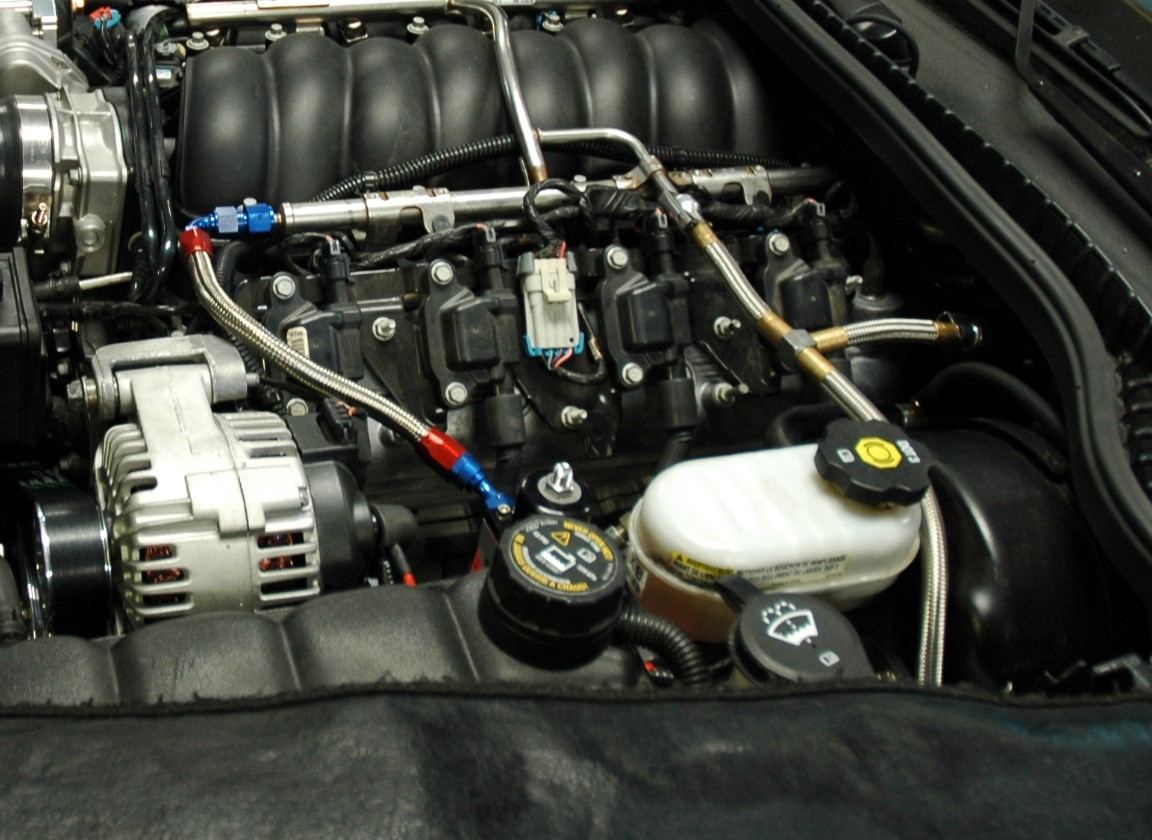
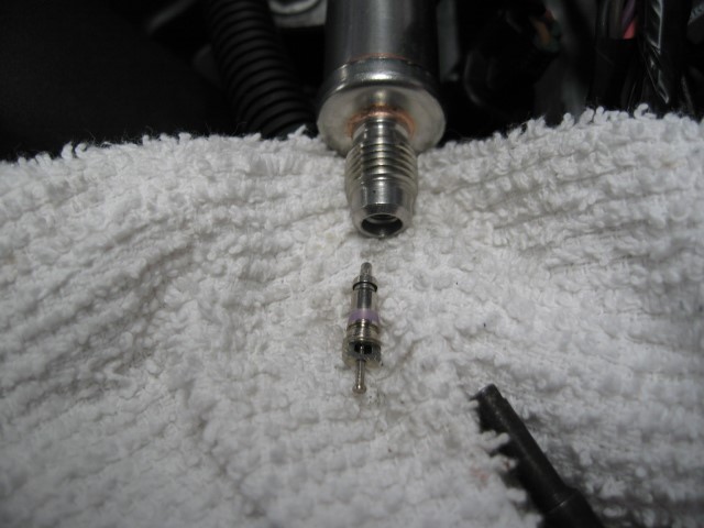
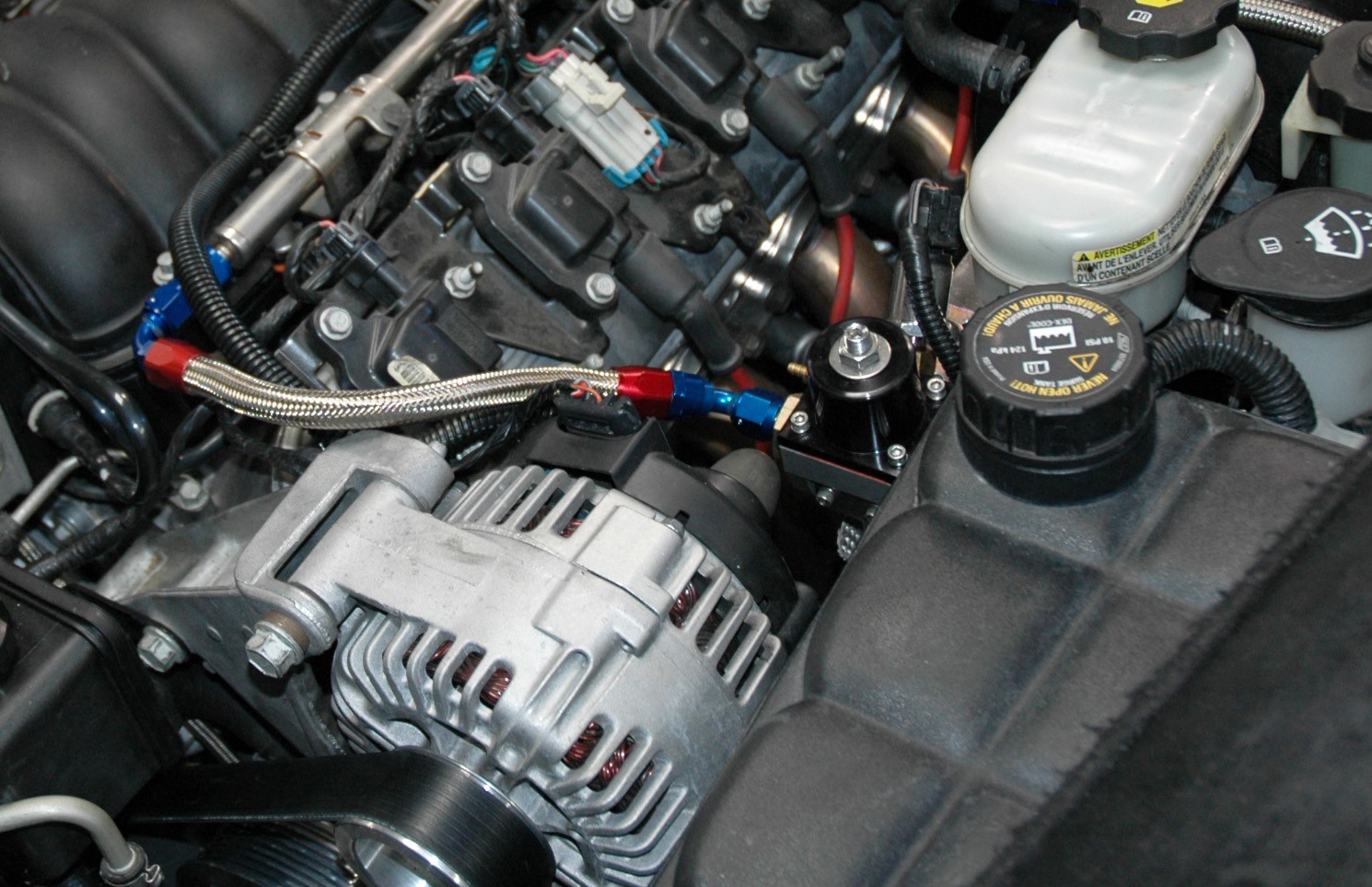
2.5 Next is the return side of the fuel system. Remove the nut attaching the master cylinder to the booster and attach the polished stainless bracket to the booster. Reinstall the nut and tighten. Remove the Schrader valve from the end of the fuel rail using a valve core removal tool and install the adapter fitting on the rail end. Attach the 90 degree end of the braided return line to the fuel rail. Attach the short return line to the fitting on the side of the regulator. The fitting on the rear of the regulator can be used for an optional fuel pressure gauge sender.
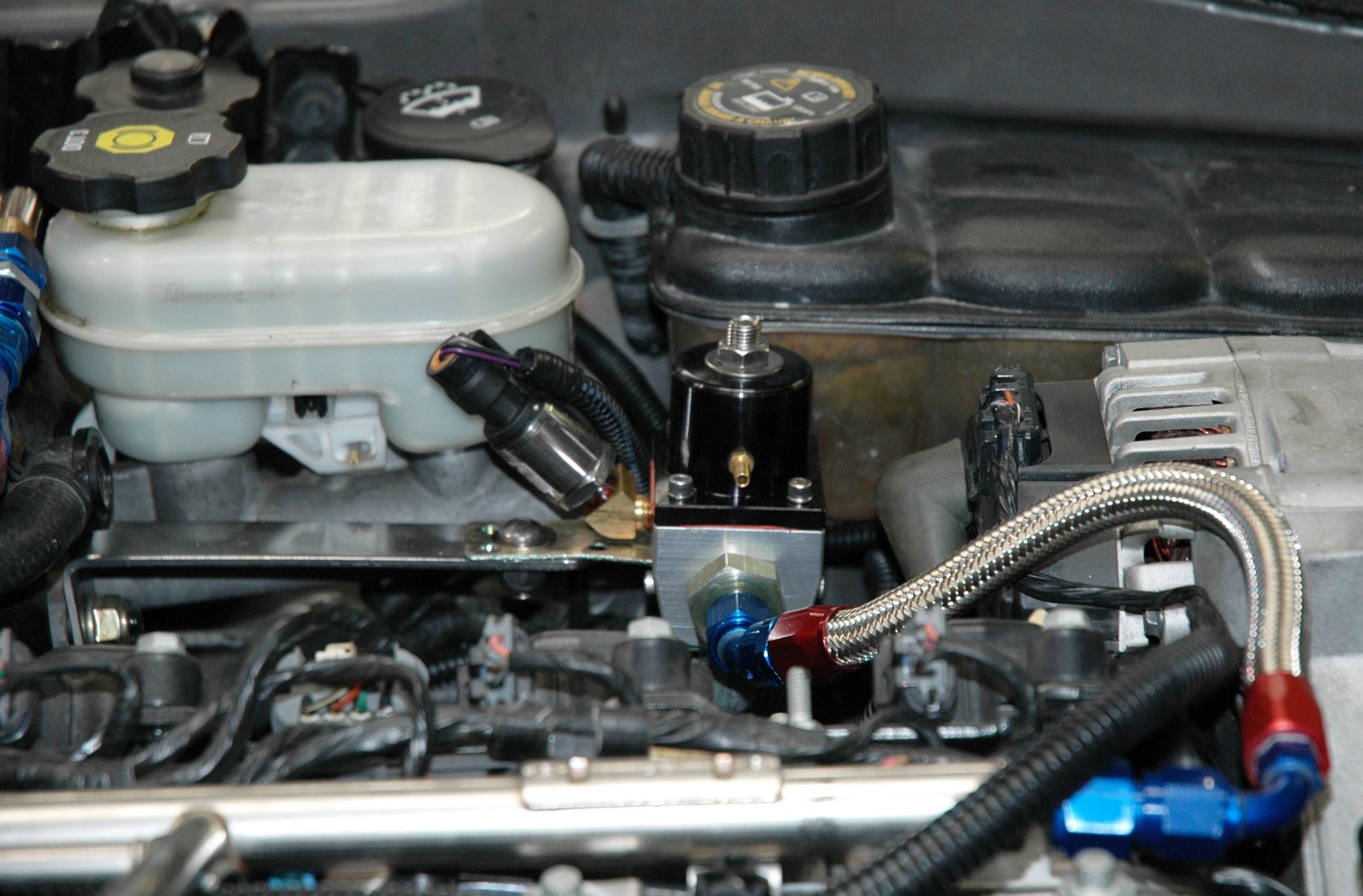
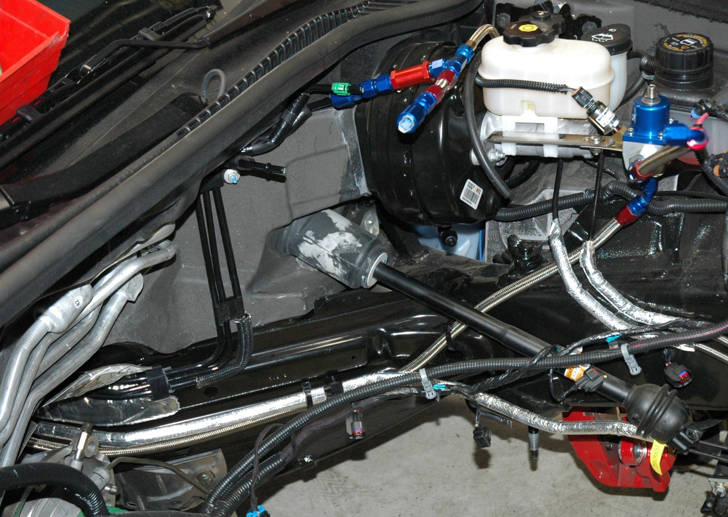
2.6 The long return line will be routed down the tunnel back to the tank. We’ve found that using a tape measure pushed through from the back works well to pull the line from the front to the back of the car. Just tape the line to the tape measure and pull it through the tunnel to the back. Again, tape over the end of the line to keep dirt out.
The end with 45 degree fitting goes in the front of the car and attaches to the fitting on the bottom of the regulator. Pull the line through to the back before attaching and tightening the return line to the bottom of the regulator. The straight end attaches to a 90 degree fitting that is threaded into the tank in the same manner as the feed line.
This line, however is 3/8” NPT and requires a 3/8” NPT (tapered) tap and a 9/16” drill bit.
Once the front is tightened then you can mark and drill the tank where the 90 degree fitting ends up. Make sure the line is secured away from the exhaust and any moving parts.
3. ELECTRICAL
3.1 Mount the relays in a convenient place under the hood. The long red wires should already be attached to the fuel pump. The relay wires with the 3/8” eyelets are attached directly to the alternator positive terminal. The other relay wires are attached to two Hobbs switches. Each Hobbs switch is plugged into a vacuum line running from a “Tee” in the brake booster hose. Find a suitable ground (NOT the valve cover or coil bracket as they are NOT grounded!) and attach the remaining wire from each Hobbs switch to the ground point. The first relay will be grounded when the switch sees about 3-4# of boost and will fire the first pump. The second switch is set for about 6-8# of boost and will fire the second pump. You can jump the switch to test the pump and connections and to set your base fuel pressure.
Make sure everything is routed where it can’t chafe, touch the hot terminal on the alternator, or run too close to the exhaust.
We want you to have the best experience possible when dealing with us both before and after the sale. You can always talk to a sales manager, the owner and head designer, or one of our techs who is infinitely knowledgeable on how the products operate and are installed. You won’t get a minimum wage customer service rep that knows nothing outside his or her script. You’ll get great advice based on many years of experience every time.
We’re happy to help you with your DIY install questions or product inquiries even after hours. The phones forward to either a Manager or Owner to help with both. Remembering that we are on Pacific time, you can generally get help until 9PM on weekdays and weekends alike. It’s something we started when the company was very young and have found it to be an invaluable resource to our customers.
SHARE THIS PAGE!